

Making The Bionutrient Meter
Two quick things before we start!
One - People familiar with manufacturing know it's easy to make 1 of something, and it's easy to make 10,000 of something, but it's a real pain in the butt to make 100. That's because making 1 thing means you just have to get it to work once. Making 10,000 means you have the time and resources to formalize the process and use large-scale manufacturing methods with big up front costs (like injection molding, etc. etc.) to make it work 99% of the time. It is our lot in life to make 100s of things :) That also impacts how we design and make the device.
Two - Just FYI, we made lots and lots of bad versions before we got something that works most of the time.
Ready, Set, Go!
Get circuit boards + test them
We have our circuit boards routed and assembled (ie parts soldered onto the board) in China by Elecrow. It comes in a big box box, and we have to check and make sure they all work. We hook each board up to a computer, try to 'talk' to it over USB, and make sure all the lights work. If they don't talk or blinky blinky, then we put it in a pile and hope we can fix it later.
However, there are 3 keys parts that we do not have Elecrow put on... the bluetooth module (which is on the back), and the two detectors. The detectors are very temperature sensitive, and we need them oriented in a weird way, so we just do that ourselves.
The bluetooth’s are soldered on-by-one and we use container boxes for each step so we know where each one is at in the process.
We use optically clear glue to stick the optical filters on the detectors. The filter ensures that Chlorophyll Flourescence doesn’t interfere with the reflectance we’re trying to see.


Meanwhile, we prepare the cases
We 3D print our own cases - for small batches it's cheaper than injection molding, and it allows us to improve and update the design with little to no cost. It does take a long time though - about 7 hours per case... but it's not like we just sit around and watch it go (though... it is really fun to watch!).

Once that's done, we prep the cases by adding the wrist strap, the tag with the device ID, and attaching the clamp and springs using glue and set screws.

Bionutrient Meter... Assemble!
Now we put the circuit board in the case. The key here is that we've done quality checks on the board and case, so we can be confident that the next step is a go. But we have one more very important little piece to add - the light guide!
The light guide is a small piece of laser cut acrylic (clear plastic) which helps keep the light focused on the sample, and the reflected light focused on the detector (where we read it). It is pretty rudimentary (but cleverly designed if I do say so myself) and pretty cheap to make in the 100s of units scale, and we can make it ourselves with no (pricey) molds. So it's a great 80% solution. This is special acrylic which is transparent to UV - it's generally used in tanning beds, so thank you tanning beds for creating the demand so we can use it also :)

Once assembled, we test the detector, update the bluetooth with the name, and save the device ID. All this is saved to the web so we can follow up on that device later if there was an issue.
Calibrate devices so they work whenever, wherever you need them
Ideally, every device we send out will give the same value when used on the same object. The reality is, it won't (and PS very very few other things you buy will either)... but it is our job to make them as close as possible, for as long as possible, and to let you know when things may be off so you can fix it. We calibrate the devices in two main ways:
Heat Calibration
LED intensity is very susceptible to temperature changes. Our own testing shows that LED intensity changes by 50% or more between 40F to 125F, and the graph below shows the variation across an even wider temperature range. So that's a big problem if we want our devices to always read the same thing... a hot day will get a very different result than a cold day.

This is 'typical', meaning every LED is actually different so you can't even really standardize the correct, you gotta do it on every device.... *sigh*
We calibrate our devices by temperature by sticking them in an oven at 45C, then a fridge at 5C, and figuring out how much that intensity changes.
We apply a signal correction based on the temperature, and then we check that our correction worked. Believe me, we only do this because we have to, it is the biggest bottleneck in the process, but it helps reduce temperature-related error from 50% to 1 - 2% for most of the wavelengths. Below is some example calibration data.


We apply a signal correction based on the temperature, and then we check that our correction worked. Believe me, we only do this because we have to, it is the biggest bottleneck in the process, but it helps reduce temperature-related error from 50% to 1 - 2% for most of the wavelengths. Below is some example calibration data.
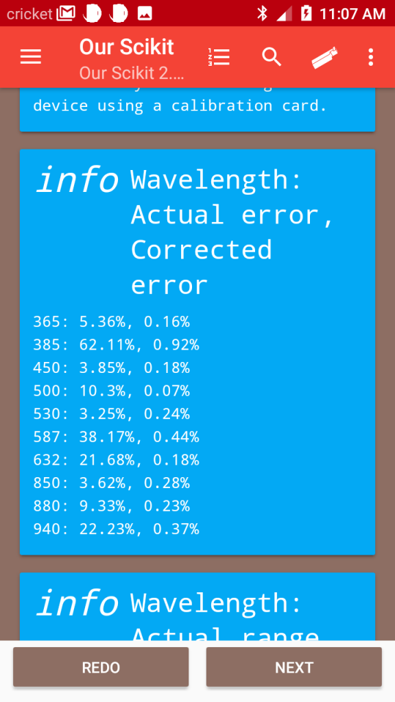
For each wavelength (365, 385, etc.) the first % is the uncorrected error - as high as 62% on some LEDs! After applying the correction the error drops to <0.5%

We literally re-heat and re-cool the device just to double check that our correction works. We still have one LED at 10%, but the rest are 3% or less... compared to before, that's a 7 - 15x improvement.
Device standardization
Reflectance values are pretty arbitrary, so we need to turn our raw detector response into some kind of standard (0 - 100) score, so that our devices always compare to each other. We use a black and white card, we call it the Master Master card, as a standard reference for all outgoing devices. That way, we can ensure that everything that leaves agrees that the Master Master card's black is 0, and white is 100.

Box, pack, ship
We then pack the devices in boxes with a USB cable, 4 cuvettes, a soil sample dish and some ball pipetters. I won't bore you with the details of shipping, but shipping in quantity is its own beast which we are working on getting down pat.
